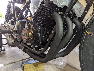
Finished Engine and Wiring

Finally got around to finishing up the engine. Used a feeler gauge to measure the gap between the cams and the shims. Ordered a valve shim tool to push the buckets down. Used my wife's tweezers to pick out the shims. Measured them with some calipers to compare them to the spec, which is .06 - .13mm. You annoyingly have to put them all back in to keep measuring them so the cams dont damage the buckets. Putting them back is NOT as casual and fun as the online videos make it look... The shims are a pretty tight fit so they kept sliding past the buckets instead of seating. There was only 1 out of 16 shims that was barely in spec, but none of them were shockingly out of spec
indicating something scary, just normal wear for a 40 yr old engine. I went ahead replaced all 16 shims to land mid spec around .09mm. To calculate each shim size you subtract your desired gap (.09mm) from your measured gap, add that to the measured shim and then round to the nearest .005mm. After putting in the new shims I remeasured with the feeler gauge to confirm I was in spec.

I freaked out because the feeler gauge wasn't going in, then I saw it was at .18mm so I flipped it to .08mm and then it still didn't fit... The oil on the gauge was holding the .10mm against the .08mm that I didn't see, so I ended up confirming again that .18mm indeed does not fit. cool cool cool. Finally measuring with ONLY the .08mm gauge, I confirmed everything was in spec. I cleaned up the cam side cover/caps and the head bolts. After fighting with the new gasket I used some bearing grease to hold it in place on the lid. I had to take off the starter solenoid I relocated to get the lid in place. I torqued the head bolts down and then the engine was done! There are some spots I need to touch up with engine paint but it looks so good.


I got through more than half of the wiring. Wiring a bike from scratch isn't the most DIY friendly activity but luckily I have quite a bit of experience in electronics and wiring panels. You'll need plenty of connectors, heat shrink tubing and multicolored wire (very important for troubleshooting). I used the wire gauges specified by motogadget (m-unit) and honda. I started by running an 8 gauge power cable from the battery location to the starter solenoid/main fuse. I also extended the starter cable and ran it to the starter solenoid as well. I connected power from the main fuse to the m-unit. I used the stock battery frame grounding wire and ran an additional 12 gauge ground from the battery to the m-unit. I wired in the keyed ignition and gave things a test.
Everything powered up correctly which was a good sign. Hiding all the electronics and wiring becomes a challenge quickly in such a cramped space. You have to be very methodical to make sure it doesn't turn into a complete mess. You can't leave a lot of extra length on your wires as there isn't a lot of space to store it. The m-unit also provided a suggested wire color chart which I followed. For anything unspecified I used the color from the Honda diagram and made sure to update my wiring diagram with every varying wire color. I used bullet style connectors, which is standard for older Japanese motorcycles. I haven't seen many cafe builds that are willing to show you the gory details of their wiring using an m-unit, but here I am, at your service.


It looks a little bit like chaos, but id like to think its an ordered chaos. Every wire color means something and nothing is hard wired in; I gave every component the chance to be replaced. I connected another ground to the m-unit and ran it up through the front of the bike. I got the reg/rec connected starting with cutting off the brand new connector, which feels horrible... Then I brought power, switched power and a ground to it. Then I cut off the spark units' connectors (ugh) and connected them to ignition from the m-unit, ground and ran the lines up to the ignition coils. I then extended the wires from the points cable, cutting off another connector, connecting the points to the spark units. The points cable also has the neutral and oil indicators which I ran up through the front of the bike for later. I grounded the ignition coils tapping into the ground line ran to the front. I connected the m-unit to the input of the starter solenoid; the output is ran to the front of the bike to connect to the clutch later. I just need to extend the alternator cable and connect it directly to the reg/rec, then the power system for the bike will be complete.
The Highsider brake light led strip came with 3m sticky foam mounting tape, which didn't work AT ALL. I ended up gluing it into place with loctite gel super glue. The rear indicators are Motorgadget m-blaze pins I installed into the old sissy bar mounts, conveniently the same tap size. I blue loctite-ed them into the right orientation in absence of a locknut. I wired in the rear brake switch, the brake light and the rear indicators. The rear indicators also connect to a line that runs up through the front of the bike to also bring power to the front indicators and the gauge indicator light. I mounted the seat and the tank to make sure my clearances were correct before I continue.
As mentioned the alternator is left as well as the front controls and the gauge. I will be finishing that up in the next couple days. The biggest thing left is rejetting and rebuilding the carbs. I need to put the oil pan and filter back on, change the fork seals and a couple other small jobs.
Were in the end days here folks. I am super excited to take this thing out for a ride.
Hope you enjoyed the sick gifs.


Comments
Post a Comment